Technical Guide
Electrical transformers
General characteristics and technical data of AB transformers
Windings
The windings of AB transformers are wound with enameled copper wire with insulation class F or H, materials approved and recognized by the UL CSA insulation system. Alternatively, they can be made with copper sheets and plates and insulated.
Rated Frequency
AB transformers are designed to operate at a rated frequency of 50/60 Hz (dual frequency).
The transformer is a static machine; therefore, it cannot change the input frequency but only modify the voltage value.
Primary Voltage and Regulation Taps
The supply voltage is designed to power the transformer. Where the primary winding has multiple input taps, AB transformers are sized to deliver full rated power across all voltages. Some of our transformer series feature regulation taps on the primary winding ±15Vac or ±20Vac (alternative adjustments available on request). These adjustments allow compensation for network variations, voltage drops in supply conductors, or secondary voltage increases.
Rated Secondary Voltage
The rated secondary voltage of the transformer is the voltage value available at the output terminals when the transformer is connected to a load that absorbs its rated power. With respect to the value indicated on the nameplate, a percentage difference of ± 5% is allowed by standards. The transformer can also be designed with a no-load secondary voltage when the transformer operates without load; in this case, the no-load secondary voltage is greater than the load secondary voltage. AB transformers manufactured for the DUO and DUOL series with dual-voltage secondary are sized to deliver full power for both voltage values. The terminal block features two windings, allowing either voltage to be obtained by connecting the two windings in series or in parallel.
Magnetic Core
Magnetic cores are manufactured with low-loss materials or with grain-oriented laminates to improve transformer efficiency.
Transformer Protection
Standards require transformer protection and prescribe that it be applied on the primary or secondary or both windings. In case of external overloads, the transformer must not be damaged. AB transformers not resistant to short circuits must be protected at the installation point with fuses or automatic circuit breakers. The time-current rating of the fuse value necessary to protect against secondary winding overload is indicated on the transformer nameplate, where the rated primary current is also shown. Upon request, transformers can be manufactured with built-in fuse holder protection or thermal protection. Protection must be implemented in compliance with the standards applicable to the equipment and installations where the transformers are installed.
Electrostatic Shield
The electrostatic shield consists of an insulated copper sheet wound with an open turn and placed between the primary and secondary windings, extending along the full width of one of the two windings.
The shield, connected to the protective ground of the installation, reduces overvoltages and minimizes interference (parasitic currents) from the primary network by discharging them to ground, preventing them from reaching the secondary user circuit. Additionally, the shield, combined with the main insulation and proper clearances, strengthens the overall insulation protection.
Potting
AB transformers are protected by class H insulating varnish. The immersion treatment ensures uniform deposition of the insulating layer on all internal and external parts; this is followed by oven drying.
This process enhances the electrical, mechanical, and thermal properties of the insulating materials used in transformer production.
This treatment enables transformer installation in tropical environments and provides resistance to high humidity levels.
Certification and Compliance
CE Marking 
CE marking certifies product compliance with the essential requirements of European Union directives..
Insulation Electrical Systems (categoria OBJY 2/8) 
Series of transformers manufactured and certified with cURus Insulation Systems mark, in accordance with the reference standards UL1446, CSAC 22.2 for low-voltage transformers.
The certification issued by UL confirms that AB trasformatori srl will manufacture these products using a combination of materials tested and verified by UL itself.
The product type is not restrictive; therefore, it will be possible to mark products of different types, such as transformers, autotransformers, and inductors, with product operating temperature in class F (155°C).
The adoption of the approved insulation system will be identified on the nameplate through the dedicated mark UL cURus Insulation SystemAB155 and file number E340840.
Certification UL 5085 (category XPTQ 2/8).
Certification issued by UL to AB trasformatori company with file number E364320. The UL mark is the most recognized and accepted safety mark in the United States and Canada. For the North American consumer, for the authorities supervising the application of local and national codes and regulations, and for manufacturers, UL represents the most recognized and accepted safety symbol throughout North America and the world.
European Norms Electrical Certification 
ENEC is a European certification mark established by European Electrical Certification Bodies that have adhered to an agreement called LUM AGREEMENT.
ENEC is a high-value technical mark based on strict certification criteria that provides guarantees not only for electrical safety but also for the performance of the electrical equipment. The mark is issued by any of the notified bodies signatory to the agreement and is automatically recognized by all others. Next to the ENEC mark, a number is placed that identifies the body that issued the certification.
KEMA – KEUR
This mark is the prestigious DEKRA certification that attests compliance with European safety standards, demonstrating the results of laboratory tests and verification of the manufacturing location.
EAC Certificate of Conformity 
EurAsian Conformity. It is certified that our transformers meet the requirements, technical regulations, and compliance applicable to the product; they can therefore freely circulate in the countries adhering to the Eurasian Customs Union, including the Russian Federation.
Transformer Protection Class
It is a constructive feature of safety equipment against dangerous currents and is divided into the following classes:
Protection Class I
All accessible metal parts of the transformer are separated from live parts through fundamental insulation. Furthermore, accessible metal parts must be connected via an earth terminal to a protective conductor (which is part of the electrical installation). All accessible metal parts are separated from live parts through main insulation. Furthermore, the transformer is supplied with an earth terminal connected to the metal parts. This connection can be linked to the earth protective conductor of the fixed installation to ensure the safety of the main insulation in case of fault.
Protection Class II
All accessible metal parts of the transformer are separated from live parts through double or reinforced insulation.
The insulation between the primary circuits and the core and between the secondary circuits and the core must be of double or reinforced type to ensure that all accessible parts of the transformer are separated from live parts. In this case, the transformer must not be equipped with an earth terminal.
Protection Class III
Protection against direct and indirect contact is based on safety extra-low voltage (SELV) supply where voltages do not exceed 50VAC and 120VDC. In this case, the transformer is a safety transformer and must not have an earth terminal.
Insulation Thermal Class
Thermal insulation classes classify insulation materials in relation to the maximum temperatures they are able to withstand over time without altering their mechanical and electrical characteristics. The product-specific standards define the maximum acceptable temperatures under maximum operating conditions for the different components in relation to the materials used for transformer construction and the relevant insulation class as follows (at ambient temperature 40°C):

The ambient temperature at which a transformer is installed affects the maximum temperatures of the insulation class that a transformer can reach at full power. The thermal class is indicated on the nameplate.
Transformer Classification According to Short-Circuit Resistance
Protection Class I
All accessible metal parts of the transformer are separated from live parts through fundamental insulation. Furthermore, accessible metal parts must be connected via an earth terminal to a protective conductor (which is part of the electrical installation). All accessible metal parts are separated from live parts through main insulation. Furthermore, the transformer is supplied with an earth terminal connected to the metal parts. This connection can be linked to the earth protective conductor of the fixed installation to ensure the safety of the main insulation in case of fault.
Protection Class II
All accessible metal parts of the transformer are separated from live parts through double or reinforced insulation. The insulation between the primary circuits and the core and between the secondary circuits and the core must be of double or reinforced type to ensure that all accessible parts of the transformer are separated from live parts. In this case, the transformer must not be equipped with an earth terminal.
Protection Class III
Protection against direct and indirect contact is based on safety extra-low voltage (SELV) supply where voltages do not exceed 50VAC and 120VDC. In this case, the transformer is a safety transformer and must not have an earth terminal.
Rated Power
Transformer power is expressed in VA. Often, the power available is expressed in Watts or kW of the load to be powered. It is then necessary to convert its value to VA, taking into account the power factor of the load and possibly its efficiency (if the power is the delivered power); that is, it is necessary to determine the power required for the power supply:
Power (VA) = Power (W) / cos φ / n% × 100
cosØ= Load Power Factor
n%= Load Efficiency Percentage
Power (VA) can also be obtained by multiplying the voltage value (V) by the current value (I):
Single-Phase Power VA = V x I
Three-Phase Power VA =V x I x 1,73
If the transformer has multiple separate secondary windings used simultaneously, the total power is the sum of the powers (VA) of the individual windings. In case the secondary winding has intermediate taps and without other specifications, simultaneous use is not possible and the full power (VA) will refer to the highest voltage of the winding. The power (VA) indicated on the nameplate of our transformers is to be considered for continuous duty.
Permissible Transformer Overload
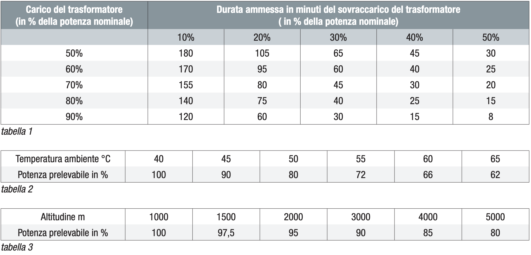
If the full rated power of the transformer is not subject to continuous use, it can be overloaded with greater power. See table 1 for details. Furthermore, the rated power on AB transformers indicates the maximum power that can be drawn from the secondary during continuous operation, without exceeding the prescribed temperature limits, in an environment with maximum temperature of 40°C and altitude of 1000 m above sea level. If conditions lead to operation beyond these limits, the power that can be drawn must not exceed the values shown in tables 2 and 3. When transformers installed in sealed containers are used, the maximum power that can be drawn must not exceed 80% of the power.
Transformer Protection Against Short Circuits and Overloads
Non-short-circuit-resistant transformers must be protected against short circuits and overloads. Protection of transformer windings can be achieved with delayed fuses (T) or with thermal-magnetic circuit breakers with delayed response curve. The size and time-current rating of the fuse value necessary to protect against secondary winding overload is indicated on the transformer nameplate.
Protection of the supply line against short circuits must be sized according to the current peaks generated at the moment of connection to the primary winding of the transformer, with inrush current of 25-30 times the rated current for approximately 10ms.
The correct selection of short-circuit protection must be made considering the case in which the short circuit occurs at the farthest point of the connection line between transformer and load. In this case, the secondary short-circuit current assumes its minimum value.
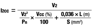
Where:
V2 = Secondary Voltage
Pn = Rated Power
Vcc = Short-Circuit Voltage in %
L = Line Length in Meters
S = Conductor Cross-Section in mm²
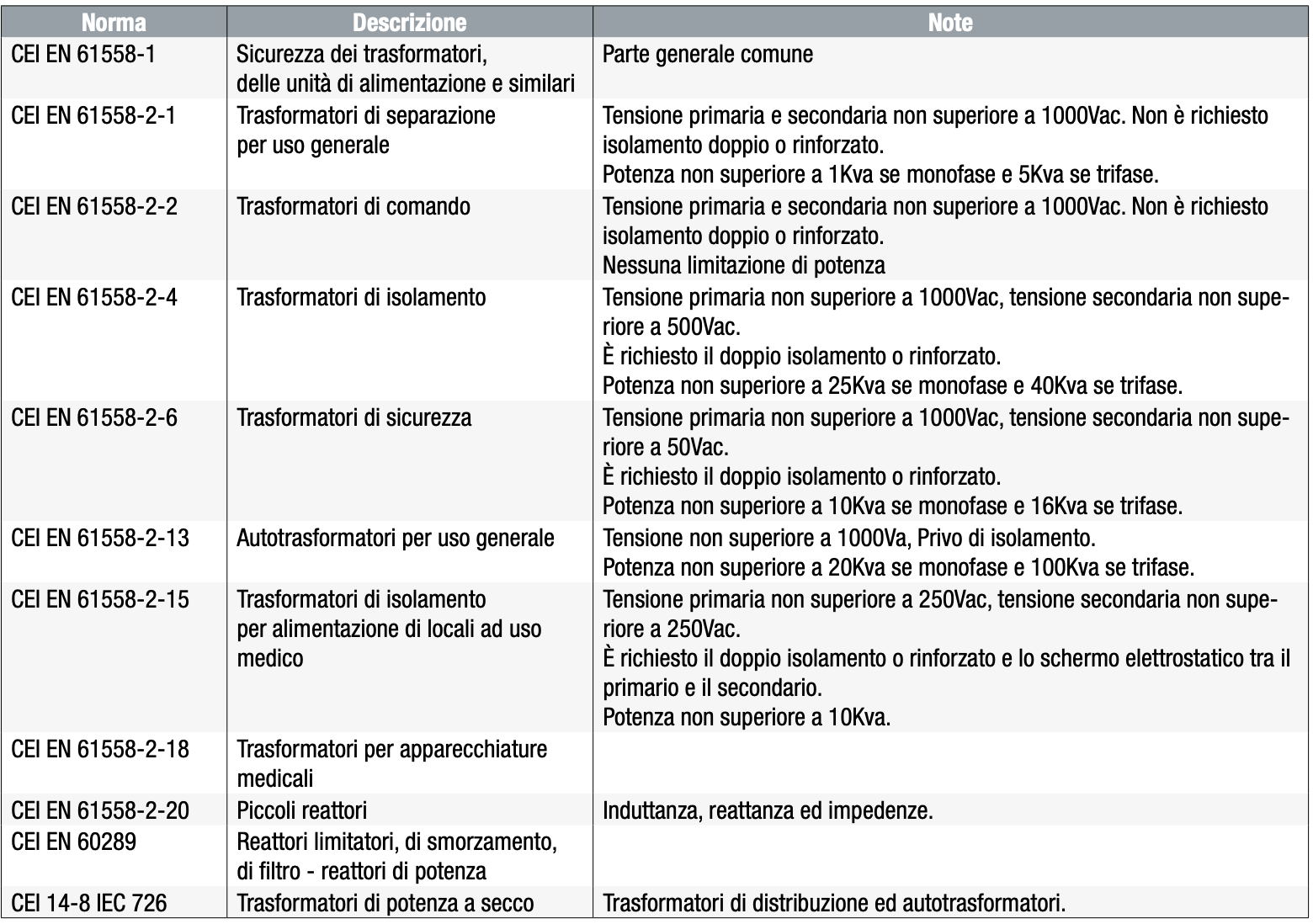
Main Reference Standards for Transformers
Transformer
A static machine operating on alternating current with 2 or more windings that, by means of the principle of magnetic flux variation over time, transforms at the same frequency a system of voltage and current into another system of different values with the purpose of transmitting electrical power.
Separation Transformer
A transformer with one or more primary windings separated from the secondary windings by means of at least one fundamental insulation.
Control Transformer
A separation transformer intended for the supply of control circuits with air and surface insulation distances multiplied by a factor of 1.4 times. For these transformers, the instantaneous permissible power must also be specified.
Isolation Transformer
A transformer in which the primary and secondary windings are electrically separated by double or reinforced insulation to limit, in the circuit supplied by the secondary winding, risks due to simultaneous accidental contacts with ground and with live parts or metal surfaces that can become energized in case of fundamental insulation failure.
Safety Transformer
An isolation transformer intended to supply circuits at safety extra-low voltage (50V no-load). Accidental contact between the two phases of the secondary winding can be tolerated without any danger to humans. Based on protection against direct and indirect contacts, the insulation class of a transformer is defined (the classification does not refer to the insulation system between primary and secondary windings).
Autotransformer
A transformer in which at least one secondary winding has a common part with a primary winding.